SERVICE 2 STROKE ENGINE OVERHUAL
2 STROKE ENGINES
Maintenance and overhaul of 2 stroke engine such as :
MAN B&W / DOOSAN:
- 26MC – 35ME – 42MC – 46MC – 50MC – 60MC – 65ME – 70MC – 72MC – 80MC- 90MC – 95MC – 98MC
- 26ME – 35ME – 46ME – 50ME – 60ME – 65ME – 70ME – 72ME- 80ME
SERVICE 2 STROKE ENGINE OVERHUAL
2 STROKE ENGINES
Maintenance and overhaul of 2 stroke engine such as
MAN B&W / DOOSAN:
26MC – 35ME – 42MC – 46MC – 50MC – 60MC – 65ME – 70MC – 72MC – 80MC- 90MC – 95MC – 98MC
26ME – 35ME – 46ME – 50ME – 60ME – 65ME – 70ME – 72ME- 80ME – 90ME – 95ME – 98ME
WARTSILA SULZER / DOOSAN:
W-X engines: W-X35 , W-X40 , W-X52 , W-X62 , W-X72 , W-X82 , W-X92
RT-flex engines: RT-flex48 , RT-flex50 , RT-flex58 , RT-flex60 , RT-flex68 , RT-flex82 ,RT-flex84 , RT-flex96
RTA engines: RTA38 , RTA48 , RTA52 , RTA58 , RTA62 , RTA68 , RTA72 , RTA76 , RTA82 , RTA84 , RTA96
MITSUBISHI / AKASAKA :
UEC85 , UEC60 , UEC52 , UEC50 , UEC 45 , UEC37
HYUNDAI :
WIN DG SERICE – RT FLEX SERICE – X SERICE –
X35 – X40 – X52 – X62 – X72 – X82 – X92
Overhaul Procedure
Checking and maintenance program by running hour timetable1- Cylinder Cover
- Pre dismantling tasks (which some of them have been done by ship’s crew)
- Setting the blocking device on the main starting valve in the blocked position.
- Engaging the turning gear.
- Opening the indicator cocks.
- Closing the inlet and outlet valves for cooling water.
- Opening the vent and drain cocks for cooling water, as soon as the cylinder cover has been emptied of water, the drain cocked is closed again.
- Closing the fuel oil inlet valve.
- Shutting off the air supply on the reduction unit for the hydraulic/pneumatic exhaust valve, and vent the system.
- Removing the cooling water outlet pipe from the exhaust valve and cylinder cover.
- Dismounting the fuel oil high-pressure pipe between the fuel valves and pumps.
- Dismounting the control air pipe from the starting valves.
- Removing the starting air pipe.
- Removing the screws which fasten the high-pressure pipe to the oil cylinder on the exhaust valve and the hydraulic activator, and lift away the high-pressure pipe.
- Dismounting the clamps from the exhaust pipe flange.
- Dismounting the screws intermediate pipe valve, and remove the intermediate pipe.
- Dismounting the spring housing and the fuel valves.
- Dismounting the protective caps from the cylinder cover studs.
- Removing the drain pipe from the cooling water connection between the exhaust valve and the cylinder cover.
- Dismounting cylinder cover nut with the help of hydraulic tools in following procedure
- eight spacer rings placing, and mounts the eight hydraulic jacks on the studs.
- connecting the high-pressure pumps to the jacks by means of the distributer block and the eight hydraulic jacks on the stud. 12-3 venting the system and increasing the pressure 12-4 loosening the nuts somewhat by applying the tommy bar through the slots in the spacer rings. 12-5 relieving the system of pressure and disconnecting the high-pressure hoses from the jacks.
- Hooking the engine room crane on to the lifting attachment on top of the exhaust valve
- Lifting away the cylinder cover complete and land it on a couple of wooden planks.
- Removing and discarding the sealing ring between cylinder cover and cylinder liner.
- Removing the protective caps from the exhaust valve studs, and mounting the four hydraulic jacks
- Connecting the high-pressure pump to the jacks by means of the distributor block and four/two high-pressure hoses.
- Bleed the hydraulic system and raise the pressure and then loosening and removing the nuts.
- Lifting the exhaust valve by crane.
- Cleaning the exhaust valve bore in the cylinder cover
- Placing the exhaust valve on a wooden support on the platform.
- Removing the nuts and the safety strap from the oil cylinder.
- Lifting away and placing the oil cylinder on a wooden support.
- Dismounting the O-ring (replace it when mounting) and the thrust piece of the hydraulic high-pressure pipe for marks.
- Checking the functioning of the exhaust valve rotation indicator.
- Loosening the screws and remove the lifting eye from the oil cylinder to gain access to the Orifice plug and the sealing oil control unit.
- Removing the sealing oil unit.
- Cleaning and unscrewing the sealing oil unit
- Checking and cleaning the bore for the orifice plug in the top of the oil cylinder.
- Sealing oil control unit checking.
- Placing the oil cylinder in a horizontal position.
- Removing and discarding the sealing ring.
- Removing the flange and taking out the piston.
- Inspecting the bore of the oil cylinder for scoring and check its measurement.
- Removing the four screws from the flange on top of the air piston, and dismount the flange.
- Loosening the air piston from the conical locking ring by means of a tin hammer, and removing the conical locking ring.
- Passing lifting straps through the four bores of the valve housing and lifting the valve housing clear of the valve spindle.
- Unscrewing and removing the lock screws which retain the bottom piece Because of being stuck tin hummer for releasing is used.
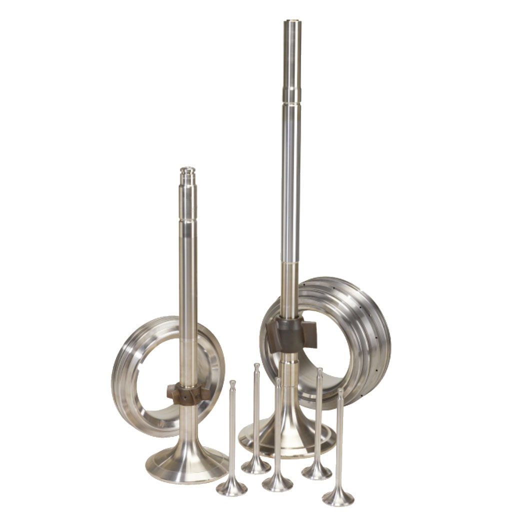
- All seats needed to be grinded as there are some dent and scratch on the valve seat, so grinding according to the manual for them have been done and below tables indicate the criteria value after grinding.
- All Exhaust valve needed to be grinded as there are some dent and scratch on it, so grinding according to the manual for them have been done and below tables indicate the criteria value after grinding.
- Valve guides are removed from exhaust valve cover by special tools, they dismantled hardly because for long time they were not dismantled and too many carbon have been accumulated in the back side of valve guides
- Placing a new sealing ring on top of the cylinder liner
- Lifting the cylinder cover by means of the crane and carefully wipe the contact surface which faces the cylinder liner
- Mounting the Cover nuts on the studs and screw down.
- Applying a coat, never Seez NS 160 to facilitate mounting and dismantling of the flange clamps
- Placing the intermediate pipe between the exhaust pipe and the exhaust valve.
- Mounting the cooling water pipes.
- Fitting and adjusting the high-pressure pipes between the fuel pump and the fuel valves.
- Fabrication Special tools for exhaust valve guide
- Valve Spindle and Bottom piece crack test with the help of UT
- Valve Spindle and Bottom grinding
- Horizontal surface lapping in valve seat
- Seat surface lapping in Cylinder cover
- Starting valve surfaces lapping in cylinder cover
- Fuel valve surface lapping in cylinder cover
- Engine rotated until piston locates on TDC position
- Stuffing box housing and piston rod screws removed
- Piston removed and placed on the special stand
- At first liner measured in different and the maximum wear of cylinder liner can be in the interval of 0.4% to 0.8% of the normal diameter and Liner measurement data record to report table.
- Oil connection and water connection dismounted
- Install of special tool for lifting on liner
- Connect the crane and load testing before lifting ( in some case , the liner is seez and need to hydraulic jack )
- The liner removed from cylinder block.
- Measurement of scraper rings and sealing ring washed with diesel oil and then checked all the defected parts replaced with new one.
- Check Stuffing springs and measuring
- Record all sizes in report table
- The liner jacket removed
- Inside the liner jacket cleaned with wire brush.
- Water connection of liner jacket is cleaned by wire brush and machining of gasket face (if necessary).
- Liner O-rings replaced with new one and coated with silicon sealant compound or oil.
- liner jacket hydro. pressure test 7bar@5min
- Dismounting the lubricating oil inlet pipe and the screwed-in pipe.
- Turning the crank throw so that it points toward the exhaust side of the engine.
- Loosening the nuts of the main bearing studs, using the hydraulic jacks.
- Rig up the tackles, two inside the engine and one outside the engine.
- Dismounting the bearing cap and taking it out
- Taking out the upper shell with using the lifting tools
- Upper shell complete inspection
- Connecting the hydraulic jacks to the high-pressure pump and lift crankshaft.
- Fastening the two wire ropes to the top of them.
- Pulling the lower shell round and up until it lies over the main bearing journal.
- Taking up the lower shell from the place.
- Measurement, visually inspect and record to report table ,
- Mounting the upper shell bearing, using the lifting tools.
- Mounting the bearing cap
- Turning the concerned to BDC
- Measuring the clearance in the crankpin bearings at the bottom of the bearing shell in both sides.
- Mounting two eye screws in the top of the frame box and suspending them.
- Mounting eye screws in each side of the crankpin bearing cap and, by means of shackles and wires, hook on the tackles and hauling tight.
- Loosening the crankpin bearing stud nuts by hydro. pump
- Lowering the bearing cap and landing on a couple of planks journal.
- Carry out the inspection of the bearing shell. The upper shell is so close to the new one without any scratches and wiping effect on it.
- Mounting the four supports for the guide shoes on the crosshead guides.
- Turning down the crank until the crosshead shoes rest on the supports.
- Adjusting the support brackets to the guide shoes so that the weight of the crosshead is distributed evenly on the four supports.
- Mounting a lifting attachment for securing the connecting rod at the lower end, on one side. Hook on the tackle haul tight.
- Turning the crankshaft until the bearing surface can be freely inspected.
- Engine is rotated to BDC position
- The bearing top clearance measured by filler gauge which is shown in below
- Wear of teeth on chain drive, 10 links measurement on tensioned chain
- The protective caps removed from stay bolts.
- Cleaning the contact face and mounting the hydraulic tool on a pair of stay bolts positioned opposite each other on the middle of the engine. Connecting the high-pressure pump by means of the high-pressure hoses, so that the two stay bolts are tightened in one operation.
- Starting the retightening of the stay bolts and proceed to tighten the stay bolts in pairs, working from the middle toward one end of the engine and then from the middle again toward the other end.
- Maintaining the hydraulic standard pressure and retightening the stay bolt nuts with a tommy bar.
- After completing the retightening procedure, mounting the protective caps.
– Exhaust valve
– Cylinder cover Mounting
– Additional jobs:
3-Piston Rod and Stuffing box
In this chapter piston, piston rod, stuffing box, pc ring, liner cooling jacket dismantling overhaul and measurement is described for one unit.Piston rod dismantling
Liner dismantling
Stuffing box overhaul
Piston cleaning, inspection and measurement
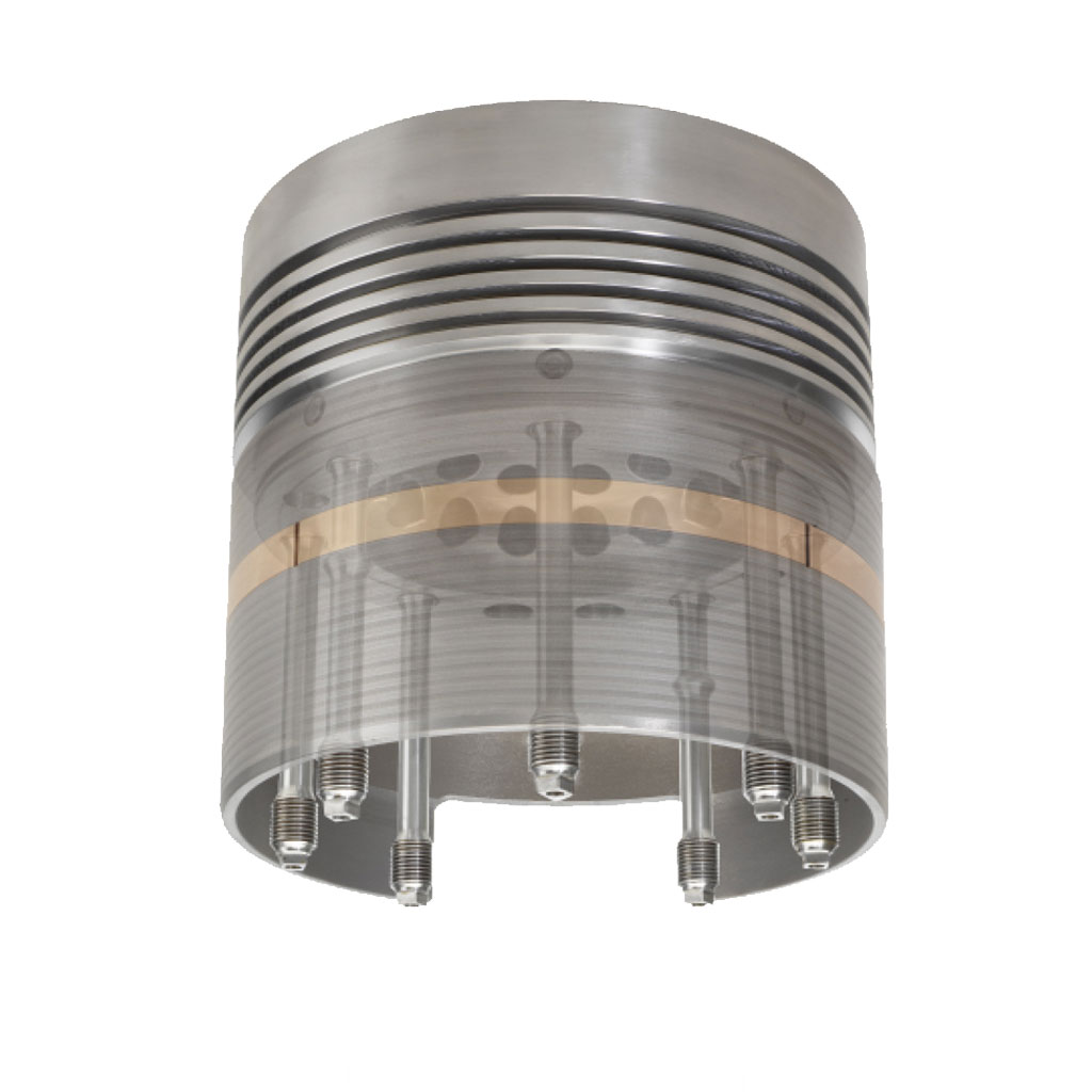
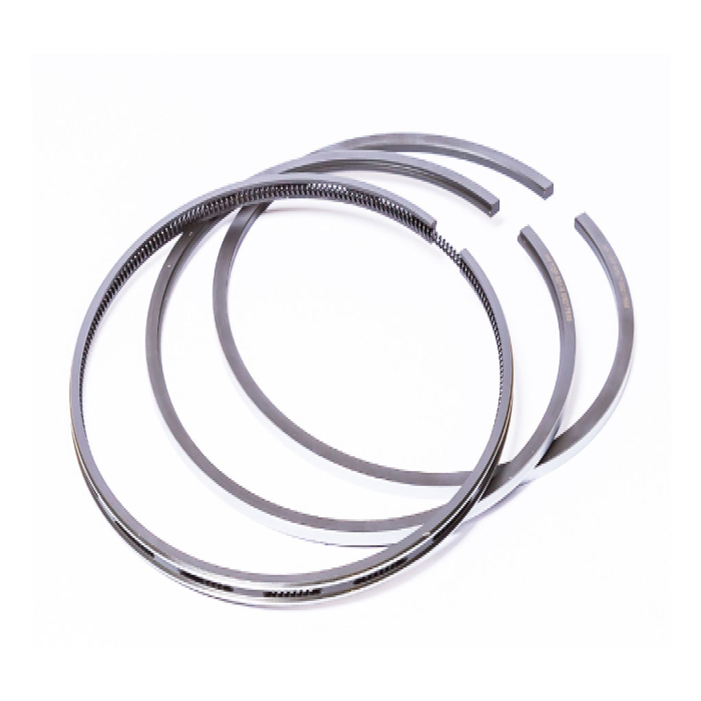
1-Piston ring, Piston crown and piston skirt is cleaned by wire brush and then with carbon remover, finally all the carbon and dirt is removed by diesel oil. 2-Piston ring, piston grooves and other sizes are measured by SEAWIDE Supervisor and is record in the report table. 3-Piston crown crack test, this test has been done by penetration and developer spray due to valid standard. Hopefully there was no defect or crack on the crown. 4- The special tools for tilting and lifting the piston rod fastened in order to place piston rod in suitable position 5-Piston skirt dismantling, all of the O-ring replaced, and finally the skirt mounted by standard torque. 6-Piston hydro. pressure test 7bar@5min 7-Piston placed on the liner 4-Cylinder Liner Liner jacket overhaul5-Main, Con Rod and Crosshead Bearing
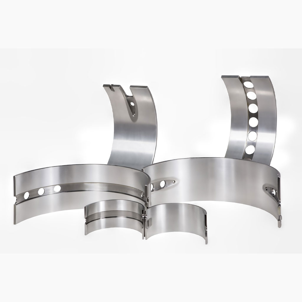
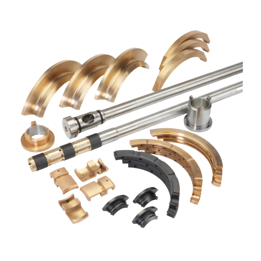
One of the most vital part in the engine is bearings. SEAWIDE inspection group carry out measurement and visual inspection for this important part.Main bearing check, dismantling and mounting
Crankpin bearing check, dismantling and mounting
Crosshead bearing inspection
6-Chain drive
Chain drive door opened and inspection for below items carried out:7-Assembly of large part
Holding down bolts and end chock bolts
The holding down bolts and end chock bolt checked and inspected for correct tightness.Retightening of stay bolts
